R & B Gas Engine This is the biggest engine that Bruce Engineering supply. Size and Weight: 2¼" bore x 2¾" stroke, finished weight 65 - 70 lbs, and will be built as the twin 12" flywheel version.
The engine is based on typical designs of circa 1900-1930 and may be run on natural gas, butane or propane. If fitted with a carburettor the engine will run equally well on petrol (gasoline). Ignition is by coil and battery but a magneto can be fitted of so desired.
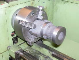
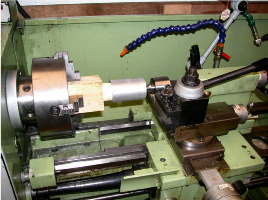
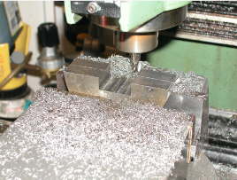
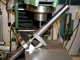
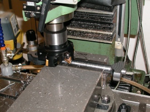
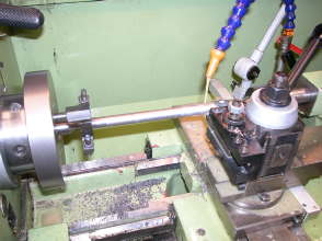
Initial photos show the machining of the cylinder block, facing, boring and completion of the mounting lugs. For an idea of scale, the milling cutter in the this picture is ¾" diameter.
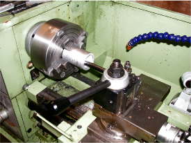
The piston is an aluminium casting and as usual these days is only just over size, certainly not enough chucking allowance. So, to get a datum, the first job was to face and centre the solid end and face and bore the the internal diameter.
Problem - how to hold the blank to enable a full length diameter to be turned? Cue my old engineering master's suggestion - a block of wood turned to a taper, the blank driven on and held tight with the centre.
Having got the o/d turned to size, now to machine out the small end lugs...
...as can been seen here.
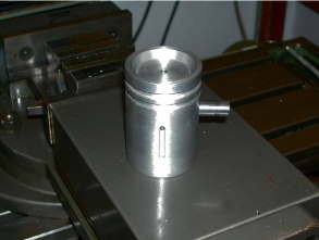
Finished piston and gudgeon pin. The combustion chamber is in the piston crown on this engine resulting in the deep dish, provision for two 3/16" wide piston rings and the lubrication slot that will allow oil from the cylinder drip feeder to get to the small end bearing.
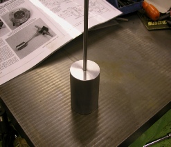
A Piece of Construction Tooling Now, here's a tip, alignment on any engine is of the utmost importance, so here is a tool that many will find most useful. A solid piece of aluminium bar is cut off and machined to a tight sliding fit into the honed bore of the cylinder. A piece of 3/8" silver steel is then push fitted into the dead centre of the bar.This tool will help with correct cylinder and crankshaft alignment and centralisation of the main bearings.
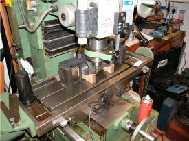
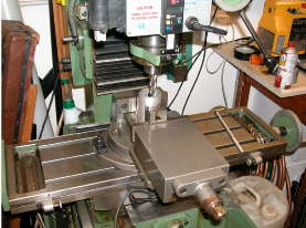
'Tramming the Mill' to ensure a perfectly flat cut when using large radius cutters.
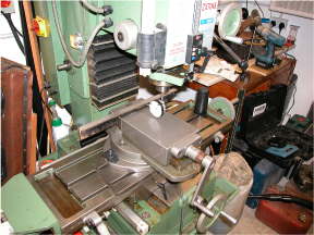
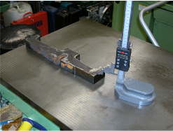
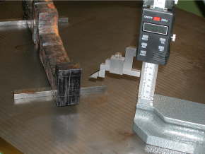
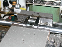
Checking vice alignment. The angle iron bar is just over 18" long and I aim to get within 0.001" over the whole length.
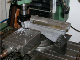
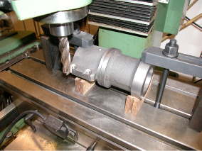
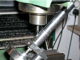
Taking a light skim cut over the engine base casting. THat's a 100mm face mill doing the hard work.
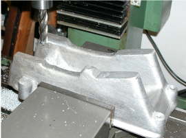
Taking the cylinder mounting bosses down to final size, height and width.
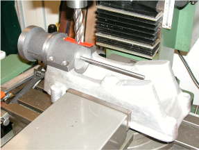
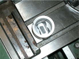
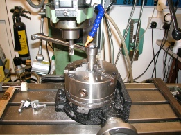
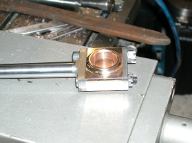
Trial fit of cylinder onto base (note test tool in position).
The following pictures are the crankshaft build, initially an 18" lump of flame cut steel. Marking out of crankshaft.
Crank and big end centres.
Set up between centres in lathe.
Rough machining big end journal.
Rough finishing the big end webs.
Splitting the disc for the balance webs.
Machining the webs to fit the crank.
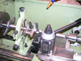
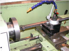
Set up for machining crank journals.
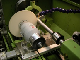
Grinding the main journals (apologies for no guard on the homemade grinder).
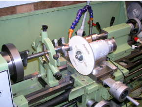
Another view of the journal grinding, note main bearing sitting on rotating centre so that it can be slid up the shaft to check fit without disturbing set up). The top slide grinder was made from a B&Q 6" bench grinder. I have a full build album if anyone wants it; very useful bit of kit.
In this series, the oil way has to be drilled from one of the crank main bearings to feed the big end bearing. Initially the threaded hole that secures the crank web is drilled deeper into the throw to just past the centre line of the big end bearing. With the crank set at an angle, a slot drill is used to form a flat.
A centre drill is used at the same setting to provide a start for the drill, the hole is then drilled to break through into the throw hole.
The crank is then repositioned to drill both the cross hole from the throw into the centre of the big end and then a second hole to break out into the bearing itself.
Finally, the flywheel keyways are cut - both ends.
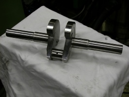
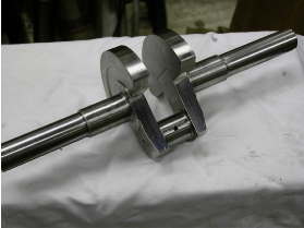
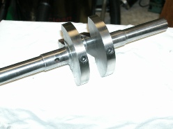
These three photos show different views of the finished crankshaft.
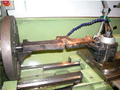
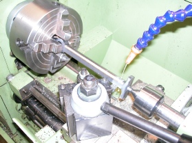
The rod is initially a flame cut blank, here between centres to rough out the overall diameter.
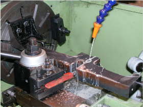
Machining both small and big ends to thickness.
Machining the back face of the big end.
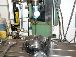
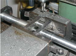
Centering the rotary table.
Machining the small end.
Between centres, offset tailstock taper turning the overall length.
Finished big end and modified cap head bolt (bottom).